Bluetooth Module Wiring Diagram
This ic made by csr is intended to be used wireless audio products just like this bluetooth speaker. Most of the bluetooth modules ships with a default baud rate of 9600.
UNDERSTANDING HC05 BLUETOOTH MODULE USING LED’S Module143

[ h g f e d c b a ].

Bluetooth module wiring diagram. A block diagram of the system is described in figure 1. Below is a list with the locations of the bluetooth module and how to bypass it. View fullsize next, we will explore the functions available to a given cc2541 ble module to change settings such as device name, sleep state, and device characteristic id.
The bluetooth modem we are dealing with has 4 labeled pins, pwr, gnd, rx and tx. Does anyone have any information on this. We have professional standard reviewers that ensure strict quality control measures in every production process.
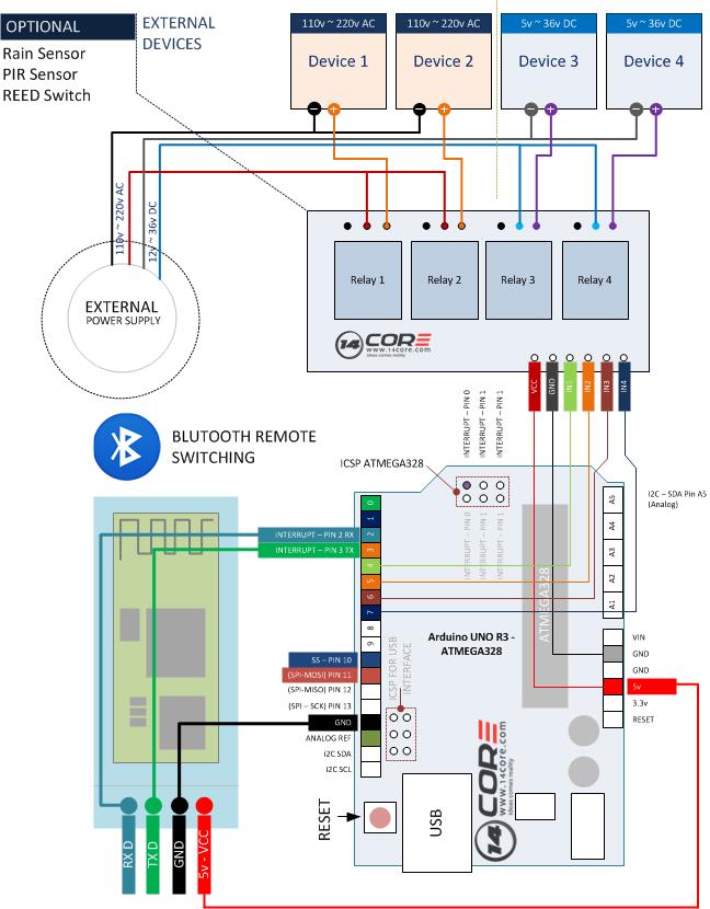
That little trick made the guide possible, and is used in this wiring diagram. By vallery masson updated on september 29, 2021 september 29, 2021 leave a comment on bluetooth module wiring diagram. The vcc pin is where the module receives its input voltage and is thus connected to the 5v pin on the arduino.
There are a couple posts on the rns install, but this will cover the 9wz vw 9wz bluetooth module with wiring harness, gprs antenna and mic. Unplug the 32 pin harness from the bluetooth module. Hi i now have alll of the parts to try this retofitting.
I recently purchased a 9w7 bluetooth module and wiring harness for a pinout diagram on the rns so it was pretty straightforward to put. We can operate the device in either of these two modes by using the key pin as explained in the. Wiring diagram wires from vehicle step 2 factory radio harness step 4 step 3 obdii connector see radio wire reference chart for.
If you want to utilize the bluetooth buttons on your steering wheel with an aftermarket radio you must bypass the factory bluetooth module. 9 rows broadcom bcm92045nmd bluetooth 2.0 module for hp/compaq, samsung and acer laptops. Then connect the rx pin to the tx pin of wiring (digital pin 3) and connect the tx pin to the rx pin of wiring (digital pin 2).
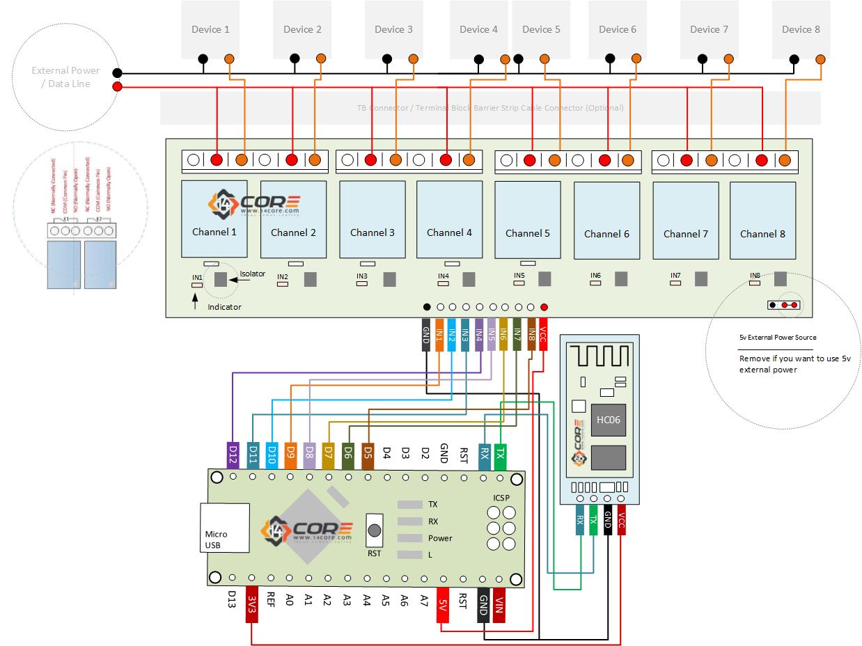
The pinout should fit these 42 devices/models. Connect the pwr pin to the 5v pin on wiring, connect the gnd pin to the ground pin on wiring. If you are going to use bluetooth connection to control and run your cnc machine, then you must change the baud rete of the bluetooth device to match with grbl firmware.
Now that your circuit is complete, test that it works (turn it on) and that it will pair with your playing device. I would really appreciate a simple text. Vcc arduino 5v gnd arduino gnd txd arduino pin rx rxd arduino pin tx key connect to the air for communication mode 10k 6 | p a g e
The bluetooth stereo headset then acts as a bridge, delivering the audio signal from the handheld device to a stereo audio amplifier and creating a wireless stereo audio system. See the vehicle wire reference chart for wiring information. An affordable communication method in pan network, with a maximum data rate of 1mb/s, working in a nominal range of 100 meters using 2.4 g frequency is a common way of wireless communicating.
Hi i now have alll of the parts to try this retofitting. The mic is already installed aswell as the handle on the steeringcollum. I have the module and the module connector and the loop connector.
Step 3 connect the orange red wire at the bluetooth module. When creating the definitive wii trimming guide, they were the ones who figured out that shorting those three 3.3v pins together forces the bluetooth module on. Hc05 module is a bluetooth module using serial communication, mostly used in electronics projects.
• connect the orange/red wire at the bluetooth module. Besides arduino, it may interface with any microcontroller such as pic and etc. I have several diagrams for the fixed line phone system but i.
Any bluetooth module you are using must use the same baud rate as the grbl firmware. I have several diagrams for the fixed line phone system but i. The use of bluetooth with 4.0 technology has been increasing recently due to its fast speed and much less power consumption.
Vh_5394 bluetooth headset wiring diagram free image wiring diagram engine download diagram. Diagram below shows the hardware connection between hc 05 bluetooth module and arduino uno. The cc2541 module can communicate with an arduino board adhering to the following wiring diagram:
A bluetooth circuit is the central part of a bluetooth and contains components such as the integrated circuit capacitors and source of power. Step 4 • plug the obdii connector into the obdii of the vehicle, under driver dash. The car is not prepared for it.
( i have changed my sound system to sony sound system in my ford fiesta plus 2015 1.5 diesel ). Bluetooth circuits a bluetooth circuit is the central part of a bluetooth and contains components such as the integrated circuit, capacitors, and power source. Hello, i am searching for a wiring diagram to connect a bluetooth/voice/usb module in my mondeo mk4.
It is pretty straight forward: See the vehicle wire reference chart for wire color and location. The bluetooth module includes information on the configuration and the setting.
The module comes in multiple communication methods but the only thing that makes it different from others is its latest technology at the cheapest rates. For this tutorial i made two example, controlling the arduino using a smartphone and controlling the arduino using a laptop or a pc.
Bmw E46 Bluetooth Wiring Diagram

Wiring & Programming Bluetooth Bee / XBEE Module with AT Command Set

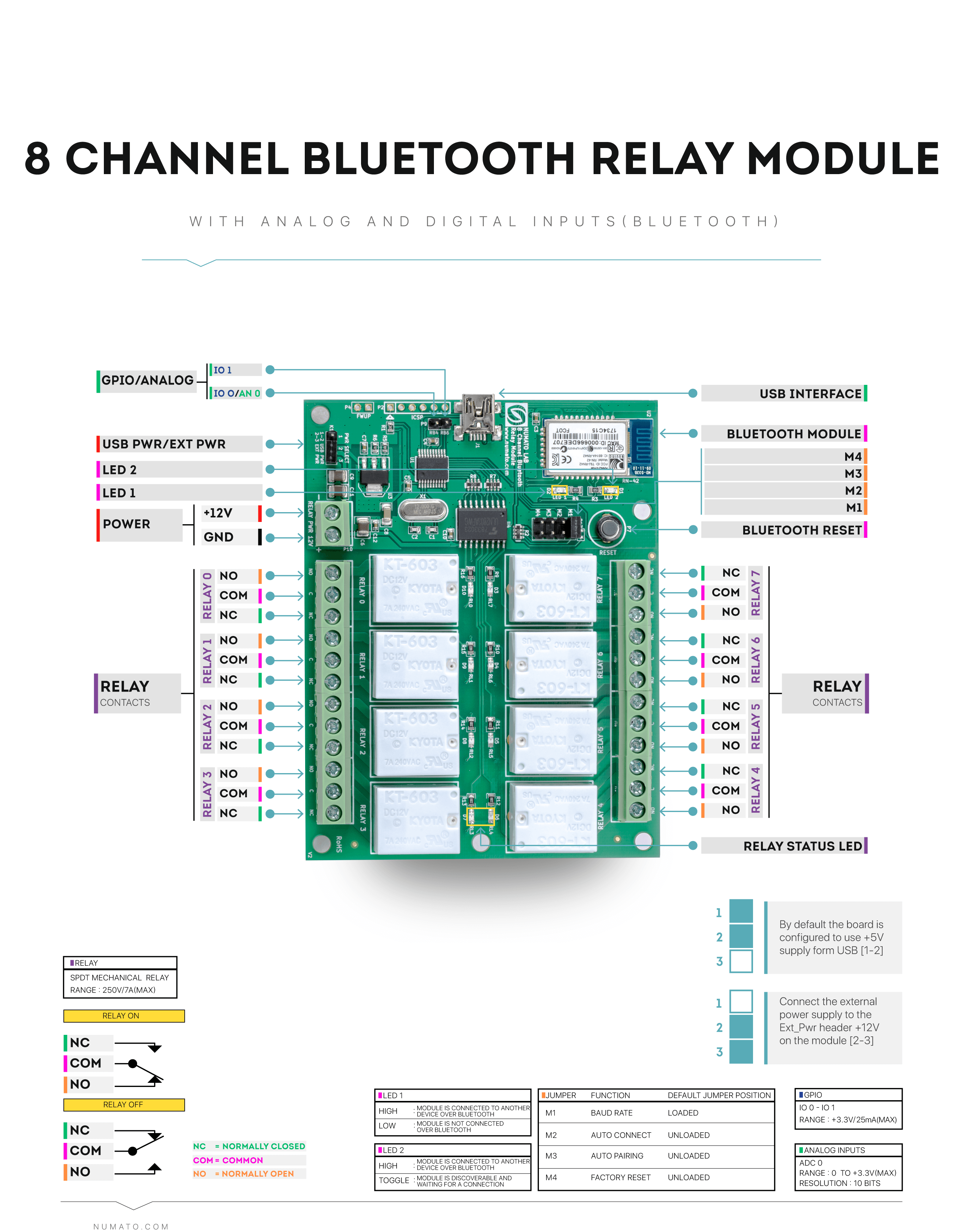
8 Channel Bluetooth GPIO Module With Analog Inputs Numato Lab

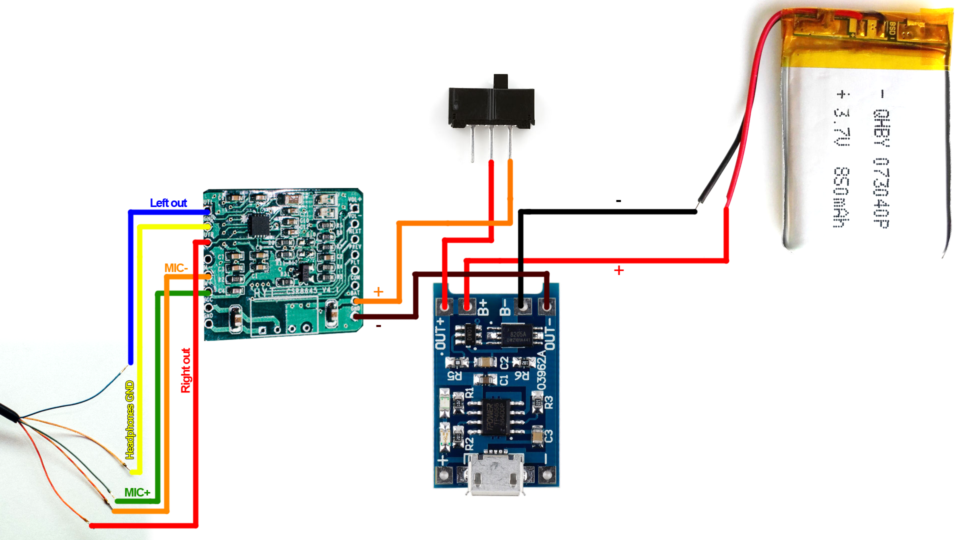
BluFi A Portable Bluetooth Audio Adapter

I would need the wiring diagrams of the bluetooth module D1BT14D212LA and radio AM5T18C815XM

Bluetooth Module Wiring Diagram Wiring Diagram
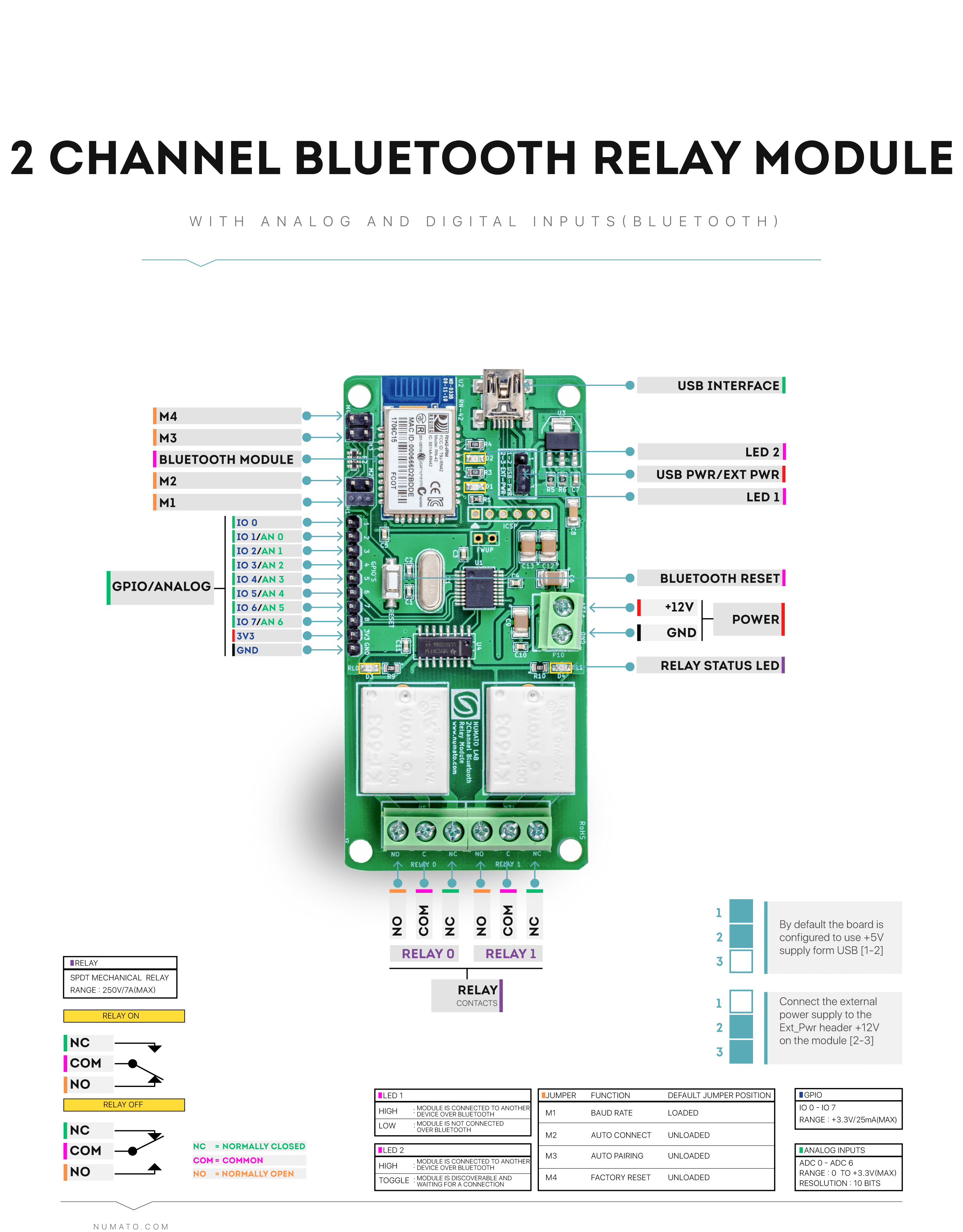
2 Channel Bluetooth Relay Module With GPIO Numato Lab
Bluetooth audio receiver The C7THN50004 chip selfdesignated WIN668
Do It Yourself Bose QC15 / QC25 Bluetooth Module
8 Channel Bluetooth Relay Module With GPIO Numato Lab
Bluetooth Module Wiring Diagram Wiring Diagram

UNDERSTANDING HC05 BLUETOOTH MODULE USING LED’S Module143

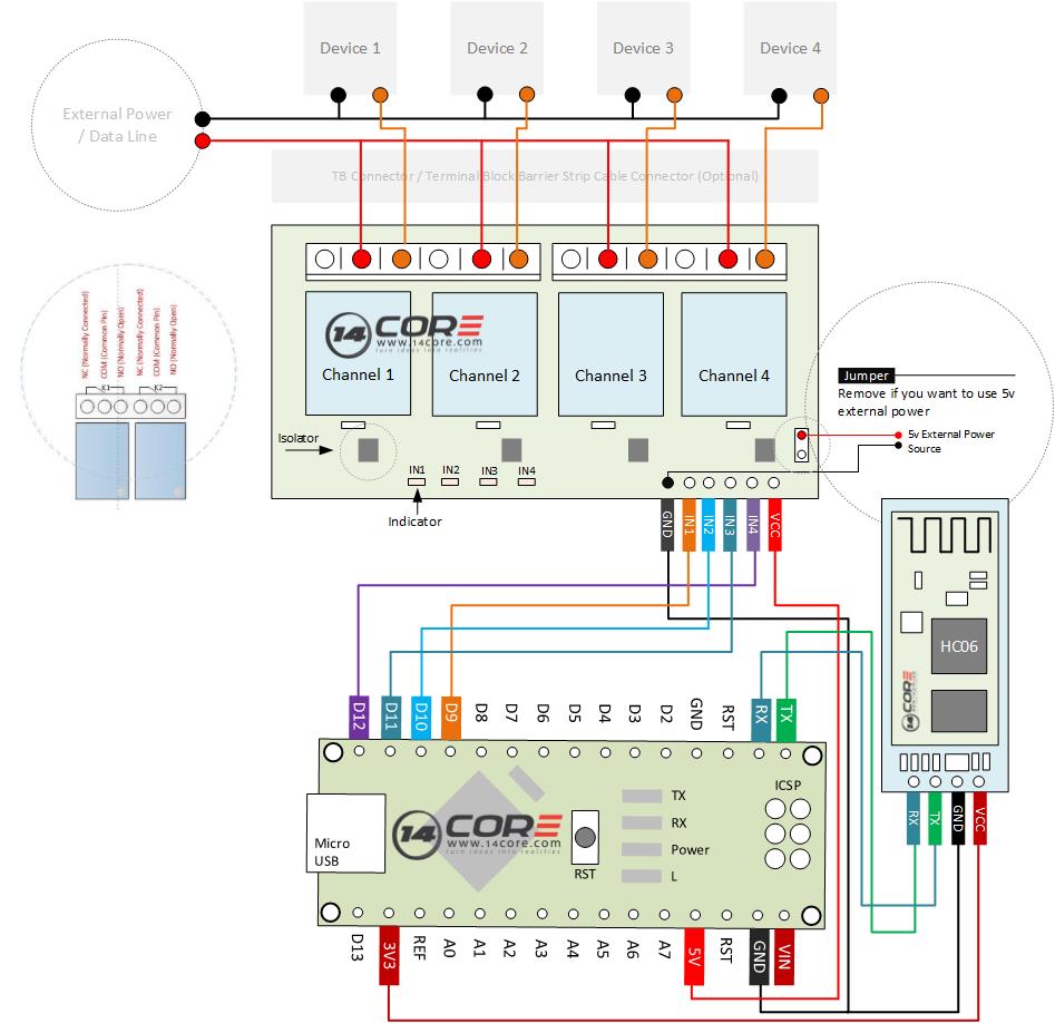
Wiring the Bluetooth HC06 / 4 Channel Relay Switching with Android
Wiring the XS3868 / OVC3860 Stereo Bluetooth 2.0 +EDR Module Board

Usb Bluetooth Wiring Diagram USB Wiring Diagram

Bluetooth Home Automation with Arduino and Android
Wiring Bluetooth Headset Circuit Diagram Wiring Schema

Wiring Bluetooth HC06 in 8 Channel Relay with Android & Arduino Microcontroller
Bluetooth Module Wiring Diagram Wiring Diagram
